A 100-Million-Revolution FORJ Endurance Test Rig — Controlling an LS L7S Servo over Modbus
In one line
An endurance rig that turns a fibre optic rotary joint (FORJ) one hundred million times. Mechanical design, machining, servo control, Android HMI, and the electrical cabinet — all built in house, five units delivered.
What the rig tests
A FORJ passes an optical signal across a rotating interface without interruption. They go into radar systems, surveillance cameras, and industrial robots — anywhere fibre has to reach something that spins.
Because it rotates, life is the question. How many revolutions before performance degrades? The benchmark is one hundred million. Even at 300 rpm that is over 5,500 hours. Nobody can stand and watch it, so the machine has to run itself, log itself, and stop itself when something goes wrong.
| Requirement | Specification |
|---|---|
| Rotation speed | 300 – 1,000 rpm, variable |
| Endurance target | 100,000,000 revolutions |
| Test subjects | Three FORJ types, swappable adapters |
| Power and signal | Through a hollow-shaft slip ring; must also run with the slip ring removed |
| Monitoring | Temperature, vibration, drive current, tilt |
The rotating assembly
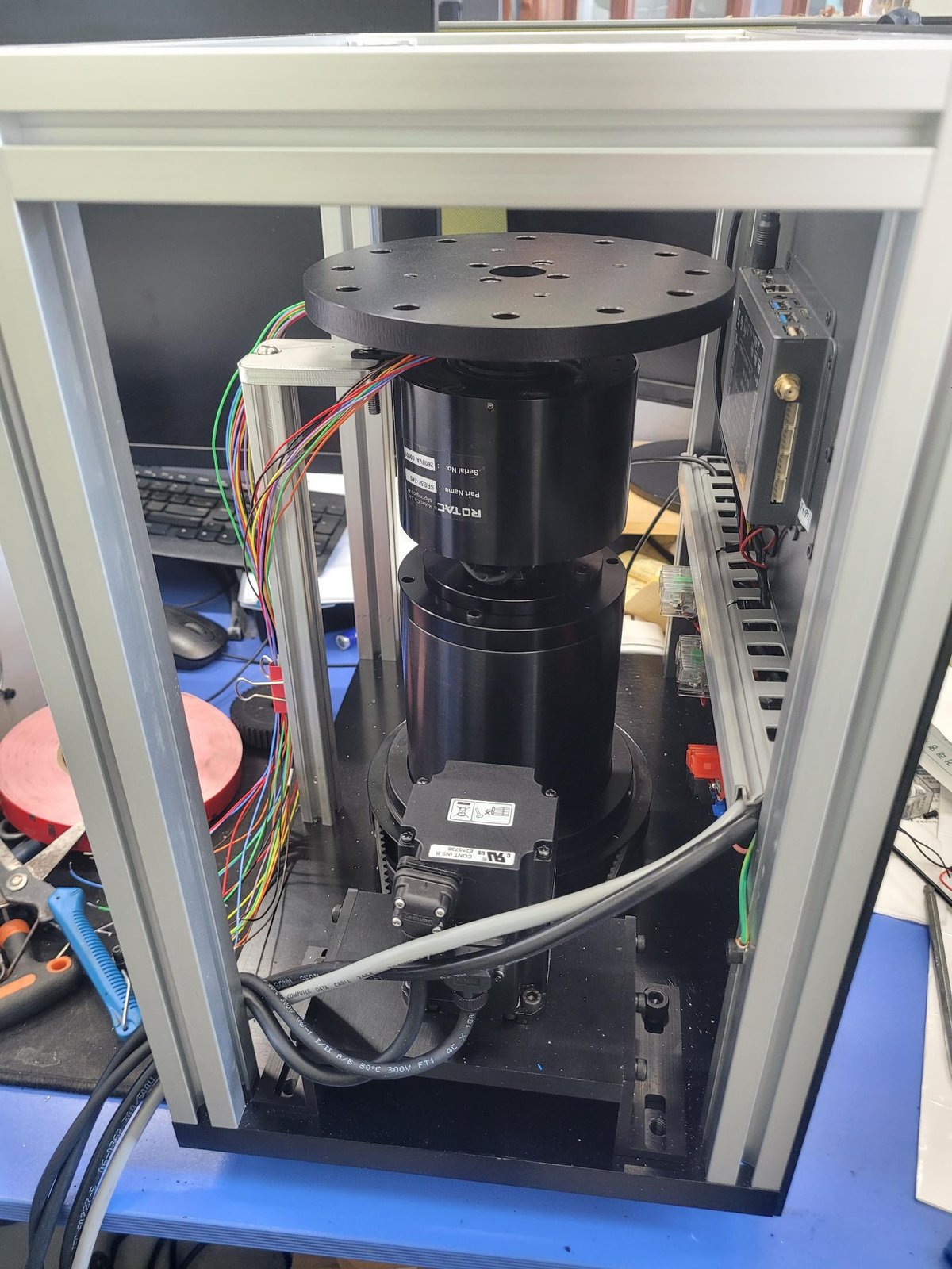
The centre is hollow, because the FORJ’s fibre has to pass straight through the axis of rotation.
From the top: the rotating plate, a hollow slip ring (ROTAC SRB50-24S, Ø50 bore), two rows of bearings, and below them a servo motor coupled by belt. The bearings are spaced apart rather than stacked, so the shaft stays true through long high-speed runs.
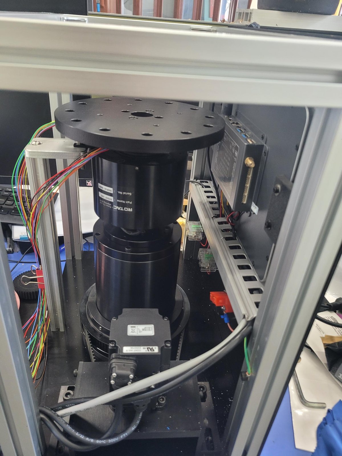
The slip ring sits on a removable adapter — the specification required the rig to run with the slip ring taken off for high-speed endurance mode.
Control architecture — a panel PC instead of a PLC
| Item | Configuration |
|---|---|
| Servo drive | LS Mecapion L7SA002B |
| Servo motor | APMC-FBL02AMK (3,000 rpm rated, 5,000 rpm max, 1.45 A rated) |
| HMI | RK3568 10.1” Android panel PC, in-house Kotlin application |
| Communication | Panel PC RS232 ↔ RS422 converter ↔ L7S Modbus RTU |
| Contacts | Servo-on, speed select and E-stop remain hard-wired |
There is no PLC. With a single rotating axis to control, a PLC adds cost and wiring for nothing. The Android panel PC writes the speed command, reads the status registers, and logs the data directly.
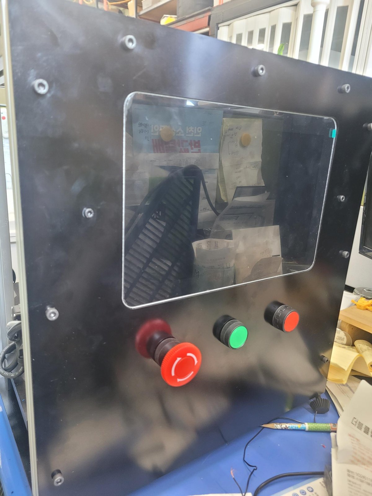
The emergency stop is the exception. It is hard-wired straight to the drive input. It has to work when communication does not.
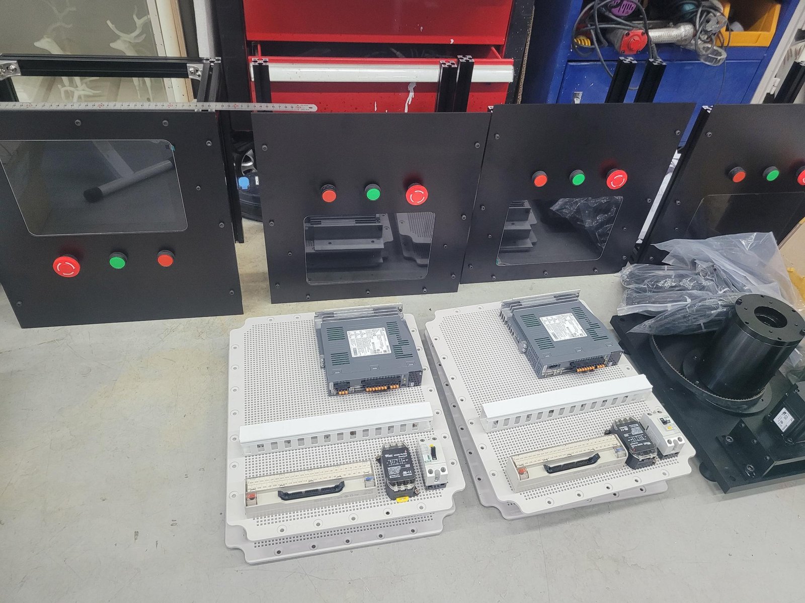
We built five cabinets, one per rig: 24 V SMPS, L7S drive, RS232-to-RS422 converter, XTB-50H terminal block, line filter, earth leakage breaker, and fan.
The HMI
The cumulative revolution count is the headline, because how far through the hundred million you are is what this machine exists to tell you.
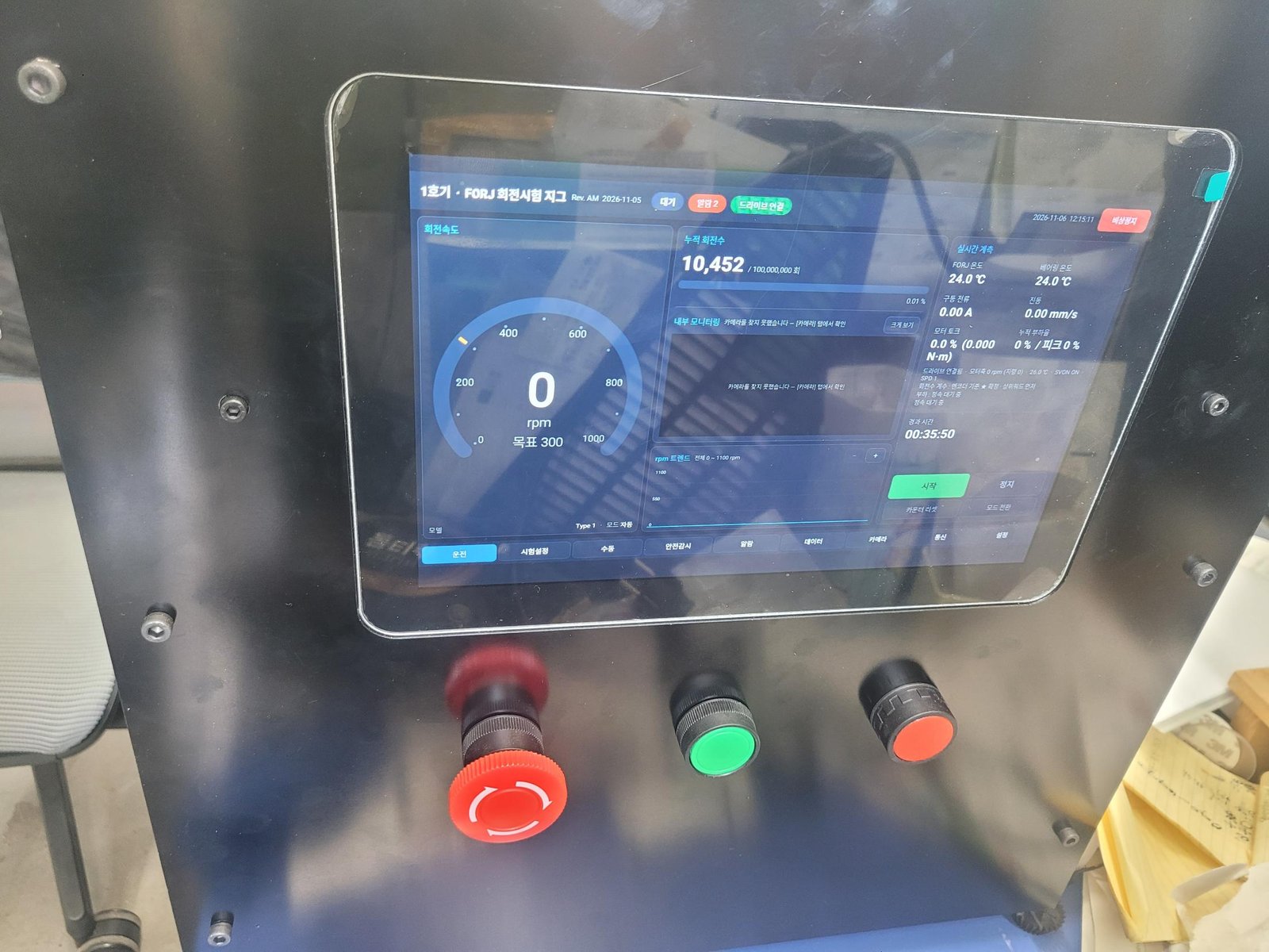
Revolutions are counted from the servo encoder — there is no separate rotation sensor. Reading the multi-turn encoder value gives the cumulative count directly, which removes one sensor and one wiring harness.
Down the right side: FORJ temperature, bearing temperature, drive current, vibration, motor torque, and cumulative load factor, all live. Nine tabs — run, test setup, manual, safety, alarms, data, camera, communication, settings.
Where the LS L7S Modbus control actually trips you up
Documentation on L7S communication control is thin. These are measured values from the real drive.
Calculating the Modbus address of an L7S parameter
The rule — group start address + index × 2.
| Group | Start address |
|---|---|
| P0 | 70 |
| P1 | 140 |
| P2 | 220 |
| P3 | 280 |
| P4 | 330 |
So P3-00 (speed command) = 280, P3-08 (acceleration) = 296, P3-09 (deceleration) = 298, P2-08 = 236, P2-09 = 238.
One exception. In the P0 group, P0-14 is an INT32, so every address after it shifts by 2: P0-15 = 102, P0-17 = 106, P0-18 = 108. Trusting the formula alone will have you writing to the wrong parameter.
Status registers are separate: St-01 current speed = 2, St-02 commanded speed = 4, St-07 current torque = 22, St-12 DC link = 32, St-14 input contacts = 36, St-19 temperature = 50, St-20 rated rpm = 52, St-22 rated current = 56. Units are 0.1 % for torque and load factor, 0.1 V for the DC link, 0.01 A for rated current.
FC03 block reads return the wrong values
Symptom — Reading several parameters in one request gives values that do not match.
Cause — On an FC03 block read the L7S returns parameters two addresses apart. Requesting consecutive registers does not give you what sits between them; it gives you the next parameter along.
Fix — Scan and verify with single reads, one register at a time. Only move to block reads once the address map is confirmed.
AL-64 appears every time power is cycled
Symptom — The rig runs fine, but AL-64 (Parameter Range) appears on the next power-up.
Cause — The application writes 0 to P3-00 when it stops. That value is saved to EEPROM, so the drive boots with P3-00 = 0, which conflicts with the allowed range (−6000 to 6000, default 10).
Fix — Set DIGIT5 of P0-17 (communication EEPROM write) to 1 (disabled). Values written over Modbus then stop persisting to EEPROM. The manual recommends this setting as well.
Servo-on is active but the motor will not turn
Two causes. We hit both.
One: the EMG contact. CN1-18 (EMG) is normally closed, so leaving it unwired means the drive sits in permanent emergency stop. In the P2-09 input logic only pins 7, 8 and 9 (CCW, CW, EMG) are normally closed. For bench testing you can set P2-09 to 11111, but restore it to 10001 and wire the real contacts before the machine goes into service.
Two: the speed select contacts. If SPD1 through SPD3 are all open, the speed command source falls back to the analogue input — and the motor creeps along on whatever offset is floating there. Keep SPD1 (CN1-23) closed.
Contact inputs are sink type: pull the pin down to GND24 (CN1-24/25) to activate. On the XTB-50H terminal block, A1–A25 map to CN1 1–25 and Bn maps to CN1 (25+n).
Reading the alarm number over communication
You cannot. The L7S has no alarm number register, and the Cn group (including Cn-02, alarm reset) has no communication addresses at all.
All you get is BIT0 of St-00 at address 0 — an alarm-present flag. The same register carries BIT1 servo-on, BIT2 warning, BIT3/4 CCW/CW limit, BIT5 zero speed, BIT6 in-speed, BIT7 in-position, BIT8 main power ready.
Alarm reset is not available over communication either. It requires the ALMRST contact at CN1-17. On an unattended machine, make sure that contact is something your controller can drive.
Choosing a pulley ratio without exceeding rated speed
With belt drive, the pulley tooth count sets the motor speed.
A 24-tooth drive pulley puts the motor shaft at 3,968 rpm at the target output speed. The APMC-FBL02AMK is rated at 3,000 rpm. That is inside the 5,000 rpm maximum, but running above rated for 1,680 continuous hours means falling torque and accumulating heat.
Going to 32 teeth or more brings the motor shaft to 2,976 rpm — inside rated. For a short-duty machine you could get away with it; an endurance rig has to be designed inside the rated envelope.
Where the RK3568 Android panel PC trips you up
GPIO numbers differ between board revisions. On the 10-pin connector, pin 1 is VCC3V3 and pin 10 is GND, with GPIO on 2 through 9. Connector pins 2 and 3 (gpio94, gpio92) happen to match across revisions, but everything from pin 4 onward is completely different. Verify on the actual board, not from the manual.
This rig uses IO2 start = gpio92 and IO3 stop = gpio94, both active low. The sysfs path is /sys/class/gpio, with value and direction at mode 666, so the application can reach them directly.
The RS232 port mapping is not in order either. The four ports are /dev/ttyS7, ttyS6, ttyS4 and ttyS3; RS485/CAN is ttyS9; TTL is ttyS0 and ttyS1.
About Poyutech
Poyutech is a smart manufacturing company based in the Gyeyang Knowledge Industry Center, Incheon, South Korea. We handle mechanical design, machining, control design, HMI development, and cabinet fabrication under one roof.
- 9 registered patents
- Registered on Korea’s public procurement channels (Nara Jangteo, S2B)
- Own products: laser marking systems (Poyumark), browser-based CAM software (PoyuCAM), 3D printing services (3D4U)
- In-house 3-axis CNC, 3D printing, and laser processing
We are a three-person company, which means the principal engineer designs the machine and answers the phone. There is no sales layer in between.
What you can hand us
| Scope | Contents |
|---|---|
| Test rigs and special machines | Turnkey — mechanics, controls, HMI, cabinet |
| Controls only | Where the mechanics exist and servo, PLC or HMI are needed |
| HMI development | Android applications or Weintek screens |
| Cabinet only | Layout design, panel machining, wiring |
| Servo communication | Adding Modbus or RS485 control to existing equipment |
No specification document is required. Tell us what you want to test and under what conditions, and we will break it into quotable pieces.
Contact
- Email — 3d4utech@naver.com
- Phone — +82-70-7510-4839
- Address — Gyeyang Knowledge Industry Center #313, Incheon, South Korea